
xStream
Capabilities
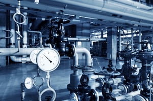
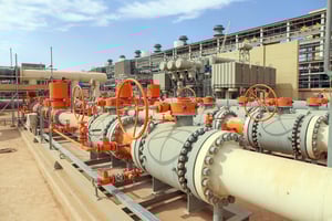
Simulate and optimize high-speed steam and gas transients to protect systems.
Trusted By


Modeling features
Compressors
- Centrifugal compressor support: Define behavior using performance curves detailing pressure or head versus flow.
- Fixed-flow positive displacement model: Represents positive displacement compressors with a constant flow output, allowing the system to determine necessary pressure rise.
- Detailed reciprocating compressor modeling: Capture physical behavior by specifying bore, stroke, clearance, rod dimensions, cylinder arrangement (single, inline, opposed, vee), crankshaft geometry, and valve timing.
- Support for single and double acting designs: Accurately model configurations that compress gas via one or both sides of the piston, including accounting for rod volume.
- Multi-cylinder configurations: Handle up to six cylinders per compressor junction, with automatic crank angle offsets and crankshaft phase shift for inline, opposed, or vee arrangements.
- Holistic transient behavior: Model suction and discharge dynamics together—pressure, flow, and energy interact naturally within the system rather than being imposed.
- Thermodynamics-based transient simulation: Reciprocating compressors drive transient response directly from their geometry and gas thermodynamics, without preset periodic flow assumptions.
- Optional frequency analysis integration: Leverage the PFA (Pulsation Frequency Analysis) module to use reciprocating compressors as pulsation sources and predict resonance effects.

Pipes
- Graphical drag-and-drop layout: Build pipe networks visually using an intuitive interface that shows inputs and results directly on the layout.
- Automated pipe sectioning: Divides pipes into segments based on acoustic velocities from steady-state calculations to optimize transient analysis accuracy.
- Standard library materials: Select from built-in pipe materials with predefined sizes and schedules, or define custom pipe geometry and accounts for scaling and roughness.
- Friction control flexibility: Choose from absolute or relative roughness, hydraulically smooth, or explicitly enter a custom friction factor for each pipe segment.
- Thermal modeling options: Apply various heat transfer modes, such as adiabatic, convective, heat flux, or heat tracing, including accounting for fluid and wall temperature changes.
- Heat capacity and tank integration: Include transient wall capacitance effects or finite tank interactions to capture dynamic thermal behaviors in piping systems.
- Flow-division modeling at junctions: Apply accurate loss correlations through tees and branches to reflect realistic pressure drop dynamics in complex networks.
- Visual feedback and validation: View pipe properties, flow behavior, and analysis output right within the schematic to catch modeling errors early and improve iteration speed.
Valves
- Valves as defined junctions: Model control or flow-restricting components at specific pipe junctions to accurately represent localized pressure losses.
- Cv/Kv and xT-based loss modeling: Define valve losses using industry-standard Cv (or Kv) values with automatic conversion and handling of both subsonic and choked (sonic) flow conditions.
- Equal percentage characteristic option: Choose valve lift profiles that increase flow rate proportionally to the previous opening, following equal percentage behavior.
- Control valves with active feedback: Specify flow-control or pressure-control behavior, where valves adjust to maintain setpoints and dynamically switch to passive loss behavior if limits are exceeded.
- Transient behavior control: Assign time-based or event-triggered valve position changes using transient data tables—ideal for simulating closures, openings, or dynamic setpoint changes.
- Check valve dynamics: Model directional flow control with user-defined closing velocity and reopen pressure differential; valve may close passively if reverse flow occurs.
- Relief valve setpoint modeling: Implement relief valves that open instantly when upstream stagnation pressure reaches a defined threshold and remain open for the simulation duration.
- Special conditions handling: Override valve states (e.g., forced open or closed) for specific scenarios or testing, and flag repeated transient data with presets to control its activation.
Flow properties
- Compressible one-dimensional flow: Solves full mass, momentum, and energy balance in each pipe segment using a modified Newton–Raphson solver paired with the Method of Characteristics for transients.
- Real-gas behavior: Accounts for non-ideal gas characteristics using a compressibility factor derived from supported property libraries, ensuring accurate thermodynamic modeling.
- Automatic pipe sectioning: Divides pipes into segments based on steady-state acoustic velocities to ensure transient fidelity without manual segmentation.
- Sonic choking detection: Recognizes and models choking when local velocities reach Mach 1, including during transients, switching to appropriate CdA-based loss modeling.
- Diverse fluid property libraries: Includes built-in standard fluid datasets plus NIST REFPROP and optional Chempak databases—enabling fluid mixtures, various equations of state, and tailored accuracy.
- Energy-conserving junction modeling: Treats all junctions except heat exchangers and compressors as isenthalpic, maintaining constant stagnation enthalpy across connections.
- Assigned flow and pressure boundaries: Supports specifying fixed flow rates or pressures at junctions—including irrecoverable losses or time-based profiles—for boundary control.
- Mixtures support: Enables definition and simulation of non-reacting multi-component gas mixtures for more complex system scenarios.

Import/Export capabilities
- Cross-product model transfer: Open models from Arrow directly in xStream.
- Import from PCF, CAESAR II, GIS, EPANET: Use a wizard to bring in piping layouts from Piping Component Files (.pcf), CAESAR II neutral files, GIS shapefiles, or EPANET files, with controls for merging, filtering, and previewing content.
- Export to EPANET: Convert xStream models back into EPANET format for compatibility with open-source hydraulic modeling workflows.
- Excel-based model control: Use the Excel Import feature to update model parameters across pipes and junctions via a structured spreadsheet—ideal for batch edits or scenario setup.
- Automated Excel exports: Configure the Excel Export Manager to send output data directly into specific spreadsheet cells or worksheets during batch runs.
- Merge external models: Integrate external model files into the current workspace using the merge tool—helpful for combining system sections or collaborative modeling.
- Force file export for stress analysis: Export unbalanced pipe forces into formats compatible with downstream tools like CAESAR II, ROHR2, AutoPIPE, or TRIFLEX for stress modeling.
- Batch scenario export: Run multiple scenarios in sequence and export output results in one pass using batch automation, streamlining multi-case analysis.

Scenario Manager
The Scenario Manager capabilities are one of the most valuable and time-saving features for system design and comparison:
- Design Iteration Tracking – Safely explore “what-if” conditions, pump failures, or demand changes without losing your base model.
- Hierarchy-Based Scenario Tree – Organize scenarios in a structured tree with inheritance to avoid repetitive data entry and maintain consistency.
- Easy Switching Between Scenarios – Instantly toggle between scenarios for side-by-side analysis, design evaluation, and troubleshooting.
- Multi-Case Modeling in One File – Store unlimited design alternatives, operating conditions, or failure scenarios within a single project.
- Input Inheritance – Share common data across scenarios (e.g., geometry, fluids) while varying only selected inputs—greatly reducing maintenance.
- Scenario Comparison Tool – Highlight differences in input data and output results across multiple cases for clear, data-driven decisions.
- Scenario Export & Reuse – Export individual scenarios or branches for reuse in other models or for team collaboration.
- Batch Run Capability – Run multiple scenarios automatically and review results efficiently, saving time during optimization studies.

Reporting features
Output
- Customizable output control: Select which parameters, units, and the display order appear in the Output window to suit your reporting needs.
- Context-aware right-click actions: Right-click on cells or headers in the Output table to change units, sort data, copy values, export to Excel, or locate the associated object in the model.
- Transient max/min summaries: View the maximum and minimum values of transient data, along with timing and location, in either detailed or summary formats.
- Output formatting options: Configure printable reports via a Print Content window, adjusting content and style (font, layout) before exporting to PDF or print.
- Quick parameter access: Highlight cells, rows, or columns to see calculations like max, min, sum, mean in the selection tab, enabling rapid insight into output data.
- Consistent scenario outputs: Save solver results to output files (.out), with distinct files per scenario for traceability and repeatable report generation.
- Initial guess update tool: Instantly transfer steady-state results as the starting condition for subsequent runs, speeding up convergence during iterative modeling.
- Adjustable display zones: Resize and collapse General, Pipe, and Junction sections in the Output window for cleaner layout and focused data viewing.

Visual results
- Layer-based visualization: Use workspace layers, such as stacked transparencies, to control visibility of inputs, outputs, annotations, and model graphics directly in the workspace.
- Color map integration: Apply customizable color maps as independent layers to visually indicate conditions like pressure gradients or reverse flow without altering core schematic elements.
- Animated transient views: Display dynamic flow and pressure changes through animation layers to watch how waves propagate in real time across the system.
- Preset management: Save and recall layer visibility settings and color/animation behavior as presets; optionally link them to specific scenarios for automatic switching.
- Interactive style control: Adjust appearance (colors, line thickness, labels) per layer, with real-time updates visible on the workspace.
- Selective visibility for clarity: Hide or show only the information you want, such as inputs, outputs, or annotations, through layer toggling to focus your analysis.
- Composed views from multiple layers: Stack standard and advanced layers (e.g., all objects, color maps, labels) to build layered visual contexts for complex systems.
- Streamlined compared to old reports: Layers replace the older Visual Reports, offering more flexibility. No need to leave the workspace to adjust what you’re seeing.

Graph results
- Multiple graph types – Create transient plots for pipe/junction data, profile views along flow paths, force vs. time charts, and frequency response graphs for pulsation analysis.
- Multi-scenario comparison – Overlay results from different scenarios in one graph to easily compare performance across design variations.
- Flexible formatting – Adjust axis styles, labels, colors; stack multiple series; or use dual Y-axes for clearer visualization.
- Graph management – Save, organize, and regenerate graphs easily using folders and templates for consistent reuse across projects.
- Annotations & data tools – Add notes, crosshairs, or annotations; display XY data; zoom into ranges with a range finder for detailed analysis.
- Export options – Copy graphs as images, export X-Y data, save in common formats like PNG or PDF, or even record animated graphs as video files.
- Animation of profile data – Animate results over time using profile graphs to observe how pressure and flow waves propagate through the system.
- Workspace graph embedding – Place graph annotations directly onto the schematic, keeping visual context and enabling side-by-side comparisons between graph and model areas.

Supported codes & standards
ASME
- ASME Steam Tables (IAPWS-IF97): Contains a built-in library based on the established ASME 1997 steam property formulation, aiding accurate modeling of steam thermodynamics.
- Gas Relief System Piping Standards: Supports industry-recognized ASME (as well as API and ISO) guidelines for safe design and analysis of gas relief piping systems.
- Applied Standards Tracking: Highlights which ASME-related standards were used for specific calculations (e.g., for valve loss models) in the Output Window, improving traceability and documentation.

Hydraulic Institute Standards
- ANSI/ISA-75.01.01-2012 Valve Flow Definitions: Uses this standard for Cv and Xt calculations in compressible flow, ensuring consistency with widely accepted valve sizing and characterization methods.
- ANSI/API 526 Relief Valve Reference: Applies standard dimensions and characteristics for flanged steel pressure-relief valves to support accurate relief system modeling.
- Hydraulic Institute Guidelines: Aligns with industry-recommended practices for pump and system design through Datacor’s active participation in Hydraulic Institute standards development.
API Standards
- API 526 (Flanged Steel Pressure Relief Valves): Supports modeling and sizing of relief valves in accordance with the dimensional and performance specifications outlined in this standard.
- API Guidelines for Gas Relief Systems: Incorporates recognized API practices for evaluating relief system capacity, piping configuration, and safe discharge conditions.
International Standards
- DIN and JIS Pipe Standards: Includes pipe material and dimension libraries from German (DIN) and Japanese (JIS) standards to support global project specifications.
- ISO Standards for Gas Relief Systems: Aligns with ISO guidelines for the design and analysis of gas relief and venting systems alongside ASME and API practices.
- International Fluid Property Databases: Supports integration with NIST REFPROP and optional Chempak libraries, enabling accurate thermophysical properties for a wide range of international applications.
Other Standards
- ASTM Material Standards: Provides pipe and material properties consistent with ASTM specifications for strength, roughness, and temperature limits.
- AWWA Pipe Standards: Includes data for waterworks piping systems following AWWA guidelines, where applicable to steam or gas service.
- MSS-SP Valve Standards: Supports valve dimension and pressure class definitions from the Manufacturers Standardization Society.